
Seismometer :: IMV SW-54 & SW-52
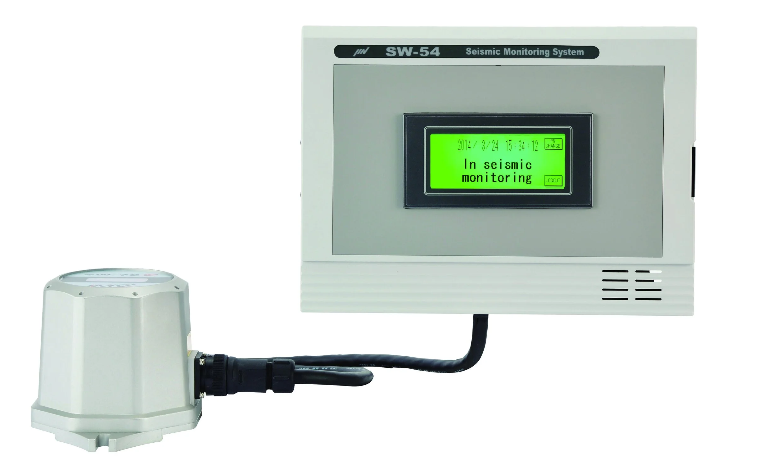
The SW series represents the pinnacle of earthquake and ground velocity monitors - high accuracy and able to detect even the smallest earthquakes, these devices are networkable and grid-controllable to enable mass surveillance of the surrounding earth. Want to measure micro-earthquakes and the effect of nearby mining operations - these systems make complex measurements simple and repeatable.
Seismometers can be connected to a central display system to comprehensively map civil construction projects and the effect they have on surrounding neighbourhoods. Each display supports up to three seismometers allowing for measurements across vertical planes.


Key Features :: SW-54 + SW-52
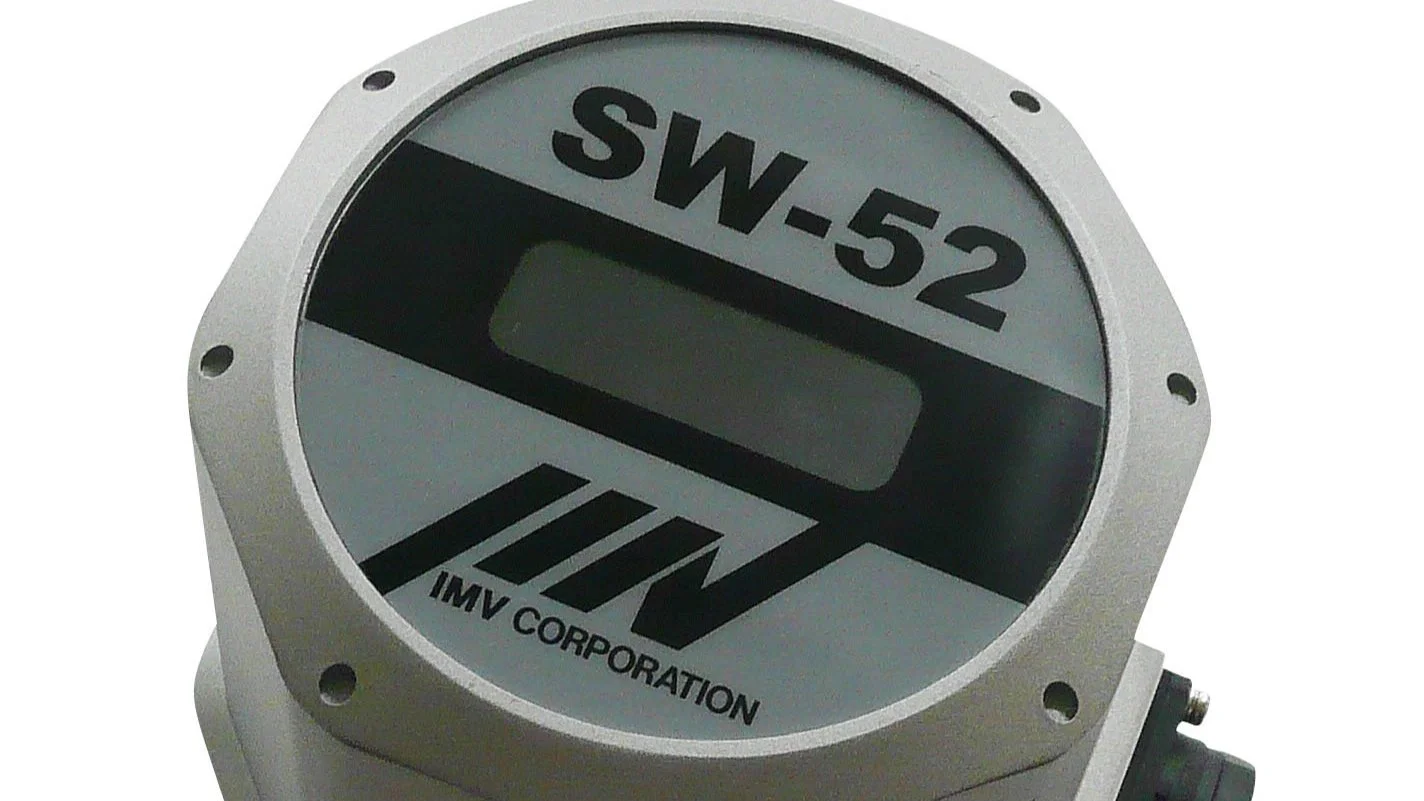
SW-52 Seismometer Sensor
The SW-52 is a cutting edge sensing element incorporating a built-in servo type accelerometer used for detecting micro-tremors. Both indication and alarm intervals can be set in 1gal increments.
With an IP67 rated design the sensing element is dust and waterproof, allowing for long-term exposure to the elements.
Fixing is simple using only two bolts, providing the rigidity required for accurate measurements.
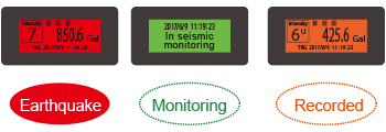
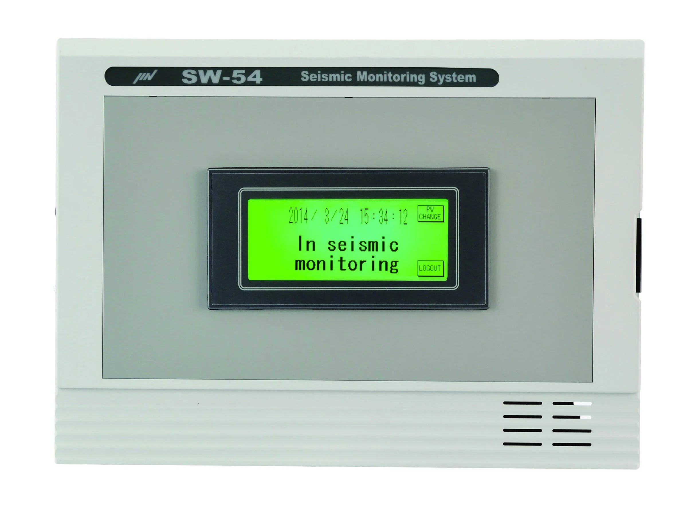
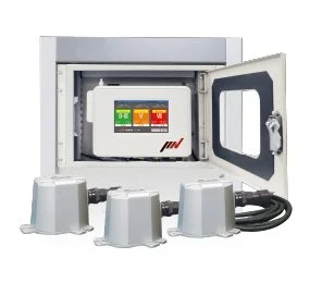
SW-54 Display States
Three display states convey simple information to the user. Green shows the device is currently monitoring and in pre-trigger mode, Red indicates an earthquake is currently occurring and Orange shows an event has been recorded.
With optional software up to 50 events can be recorded for later analysis.
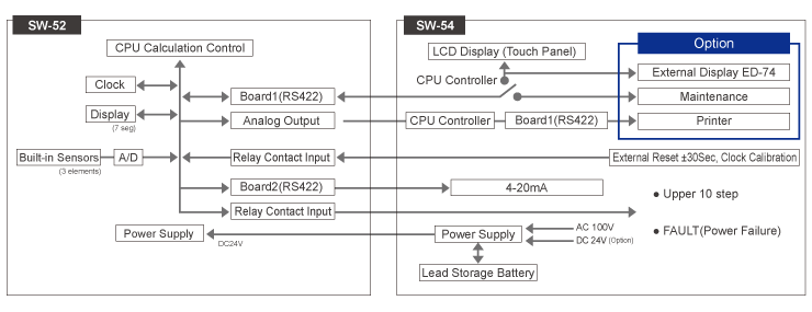
Complete System - Block Diagram
The coupling of an SW-54 with SW-52 provides a comprehensive solution for on and off-grid monitoring of earthquakes. The system can be synchronised with external clocks, alarms and optional extras including displays, printers and external computers.
Additionally, up to three systems can be networked together.

Available in Flame-Proof / Dust-Ignition-Proof Forms
SW-52EX / SW-52ST ATEX can provide alarm outputs for control in the event of an earthquake on gas and dust explosion areas such as mining, petrochemical or hydrogen plants, manufacturing plants, etc. High resolution servo accelerometer enables to prevent secondary disasters caused by earthquakes.
Multiple Seismometer Display
TM-0013-SW is a multi-seismometer display for up to three sensing elements. The system allows for the implementation of 2/3 measurements for certainty of seismic activity.
It is a high precision seismometer employing the servo accelerometers that can detect micro earthquakes.
TM-0013-SW is the display record system for a dust-explosion-proof type seismic monitoring system SW-52EX and standard seismic monitoring system SW-52ST. This display can be connected 3 systems, also can display and record the seismic information of 3 systems. It acquires waveform and can output after logical judgement (AND/OR/2 out of 3) against seismic alarm
Seismometer Display Specifications :: SW-54
| Item | Specification |
|---|---|
| Display Element | STN monochrome LCD with touch switch/back light color: green/orange/red |
| Earthquake monitor display | Present time |
| Earthquake generation display | Earthquake generation time, maximum acceleration, seismic intensity scale, alarm operation |
| Alarm hold display | Above + reset button (whole reset of alarm/buzzer) |
| Setting display | Trigger, alarm, date and time |
| Maintenance display | Pickup test, earthquake history |
| Alarm and buzzer - limit | Upper limit 3-step (ALM1‒3), individual setting, buzzer for point, |
| Alarm and buzzer - scale | Alarm setting value: 0.1 to 999.9 (gal/seismic intensity scale/Kine) |
| Alarm and buzzer - interval | Setting interval: 0.1 step,0.0 is alarm operation OFF |
| Alarm and buzzer - intensity | (seismic intensity scale alarm is set byinstrumental seisimic intensity value) |
| Alarm step | Upper limit 7-step (ALM4‒10), individual setting (acceleration/seismic intensity scale/SI value/any setting is possible) |
| Alarm setting value | 0.1 ‒ 999.9 (gal/seismic intensity scale/Kine) setting interval 0.1 step,0.0 is alarm operation OFF (seismic intensity scale alarm is set by instrumental seismic intensity value) |
| Alarm contact | 1a contact (photo MOS relay) independent COM 2-point (ALM1‒5, ALM 6‒10, each 1-point) |
| Contact rating | 200 V – 0.65 A (AC/DC, peak value |
| Alarm and buzzer reset method A | a. Automatic reset by an internal timer 1 – 9999 sec. (setting interval 1 sec., 0 is automatic reset OFF) |
| Alarm and buzzer reset method B | b. External reset terminals (all steps reset by non-voltage [a] contact) |
| Alarm and buzzer reset method C | c. Reset button on the touch panel (effective on display alarm) |
| FAULT alarm | (Power failure) 1a/1b contact switching type |
| FAULT contact | Contact rating: 2 A 30 VDC (maximum allowable voltage/current: 220 VDC/2 A) |
| Serial output - maintenance | For maintenance (conforms to RS232C ) : MC1 (switch over) |
| Serial output - external display | For external display (conforms to RS422) : MC2 |
| Serial output - printer | For printer (conforms to RS232C) : MC2 |
| Back up unit | Backup time › 10 min. (ready time), charging time ‹ 48 hours (no function at the operation by optional power 24 VDC ) |
| Mounting method | Wall hanging |
| Operating temperature range | 0 to + 50 °C |
| Operating humidity range | 10 to 85%RH (non-condensing) |
| Power supply | DC24 V ±10%, less than 70 W |
| Mass | Approx. 3 kg |
Seismometer Sensing Element Specifications :: SW-52
| Item | Specification |
|---|---|
| Detecting method | Omni-directional, non-directivity detection by vector composed acceleration |
| Built-in pickup | Force-balance servo type accelerometer |
| Frequency range | 0.3 to 10 Hz ±10% |
| Acceleration range | 0 to 5000 gal (3–component vector product) |
| NS/EW direction: ± 3000 gal, UD direction: + 2000 to - 4000 gal | |
| Low pass filter | 30 Hz (-3 dB), 4th butterworth |
| A/D converter | 16 bit, 100 Hz sampling |
| Display | 7-segment LED, 4-digit display (xxx.x or xxxx) |
| Alarm step | Upper limit 3-step (ALM1–3) |
| individual setting | |
| Alarm setting Level | 0.1–999.9 gal *1 |
| setting interval 0.1 step, 0.0 is alarm operation OFF | |
| Alarm contact | 1a contact (photo MOS relay, COM common) |
| Contact rating | 200 V- 0.65 A (AC/DC peak value) |
| Relay | Made by Panasonic PD1a type (AQY277A) |
| Alarm reset method | a. Automatic reset by an internal timer 1–9999 sec. |
| (setting interval: 1 sec., 0 is automatic reset OFF) | |
| b. External reset terminals (all steps reset by no-voltage a contact) | |
| DC output | DC4 – 20 mA, load resistance < 300 Ω |
| Full scale: 10 to 3000 gal (setting interval: 1 gal) | |
| Serial I/F | Communication with SW-54 |
| (conforms to RS422) /For maintenance (conforms to RS232C) | |
| Clock Accuracy | ‹ 70 ppm (daily error of 6 seconds) |
| Time calibration | ±30 sec. correction (external input of no-voltage a contact) |
| Operating temperature range | 0 to + 50 °C |
| Operating humidity range | 10 to 100 %RH (non-condensing) |
| Power supply | DC24 V ± 10% less than 10 W *2 |
| Structure | Waterproof (equivalent to IP67) |
| Material | Aluminum die-casting |
| Mass | Approx. 1.5 kg |
| Mounting method | Installation on the ground (fixed by anchor) |
| I/O cable | Waterproof connector |
| One-touch lock connector (made by Nanaboshi Electric) | |
| NRW-2421PF11 (connector diameter: approx. 34.1 mm) | |
| Twisted cable with shielded (made by Fuji Electric Wire) | |
| FKEV-SB 0.3sq×10 pair (outer diameter: approx. 10.5 mm) |
Want to simulate earthquakes instead? Head over to our shaker systems.