
Vibration Controller (IMV K2+)
The latest MiMo vibration controller from IMV Corporation with enhanced usability, increased test performance and enhanced network functions. Control up to four shakers with one controller, and get up to 20 monitoring channels in a single 3U box. Precision on-chip 32 bit ADCs and DACs ensure excellent control accuracy over a wide dynamic range.
The K2+ is the latest IMV vibration controller that has further evolved the usability and test performance of the K2. Network functions have also been enhanced, making it easier to connect to various devices, including personal computers and remote monitoring systems. In addition, it is 100% compatible with the previous K2 model, and test definitions from the K2 can be used within the K2+. All K2+ hardware and software are developed in-house by IMV Corporation in Japan, and we constantly strive to improve them whilst incorporating the latest technology and customer feedback.
The parallel terminals allow easy connection of additional measurement equipment, for example to record time and date or to evaluate test data within dedicated hardware and software for the specimen under test. For sensitive applications such as satellite testing, your time domain can then back up data for post processing.
All your vibration testing staples are here - Multi-axis, 3-axis, Sine, Random, Sine-on-Random, Random-on-Random, Shock, SRS, Resonance search and tracked dwell, sine burst and sine beat, etc.


Feature Summary

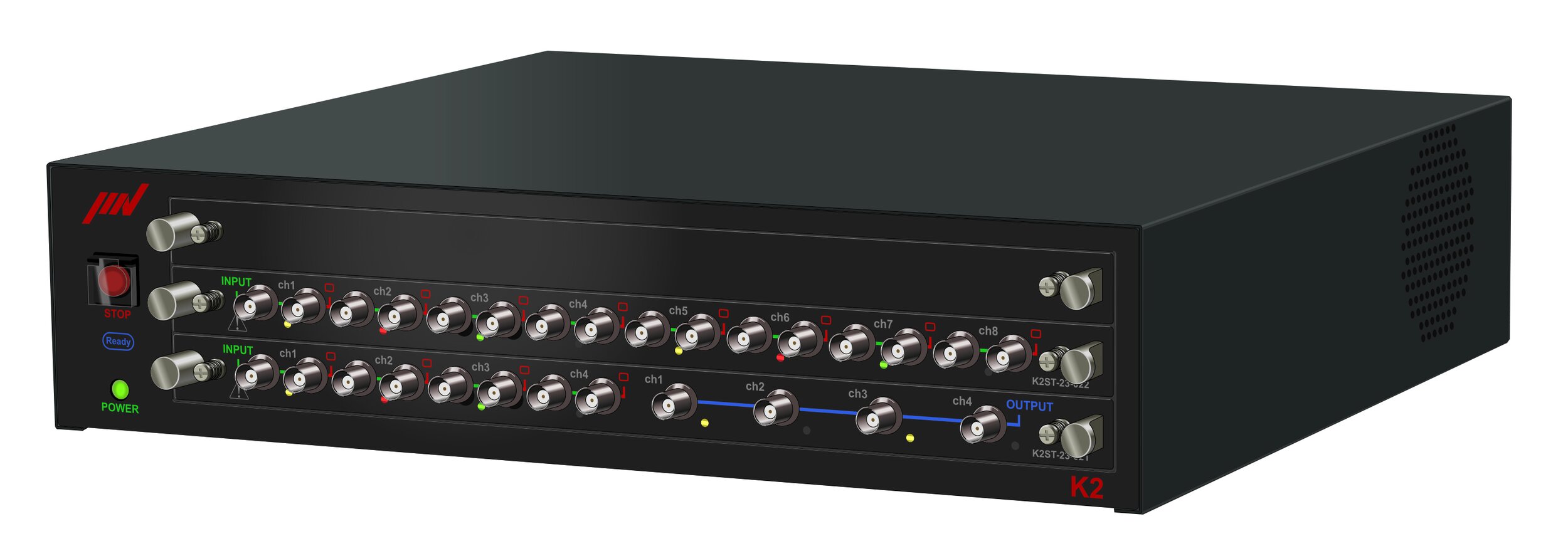
System Composition
The K2+ is a full-featured vibration controller that interfaces in closed-loop mode to the electrodynamic shaker. Multiple accelerometer types are supported and each input is able to be fed out again via a parallel terminal.
The parallel terminals allow easy connection of additional measurement equipment, for example to record time and date or to evaluate test data within dedicated hardware and software for the specimen under test. For sensitive applications such as satellite testing, your time domain can then back up data for post processing.
A total of 20 channels of input monitoring are available in the 3U form-factor and up to four shakers can be controlled from the main IO card.
The large connector on the back of the K2+ is for combined controller when combining a shaker with an environmental test system.

Ethernet Connectivity
The K2+ uses Ethernet, so installation is easy and a laptop can be used for operation. IMV secures your tests' data accuracy, providing a solution that reduces the risks of using long cables. The conditioner is as close to the sensor as possible. You can also easily control K2+ applications from your own software using simple XML commands*.

IMV Controller History
IMV has been designing in-house vibration controllers since 1994 where the F2 came to life. The following 30 years have seen development continue at pace, culminating in the release of the K2+ in late 2020.

Test Standards
A test file is automatically generated upon selection of the test conditions defined by test standards. Minimizing control error is key for a good vibration control system, and for this reason we have included major vibration standards in the K2+ Quick Launcher software option. This will prevent the operator from accidentally choosing the wrong profile. Refer to optional standards table below.
K2+ Main Specifications
| Main Enclosure | |
|---|---|
| Number of Slots | 3 |
| AC Power | Single-phase AC, 100 V-240 V (auto-selected) |
| External Communication | Contact I/O (for emergency stop) |
| Ambient Conditions | 0-40°C, below 85% RH, non-condensing |
| Dimensions | W 16.9 x H 3.9 x D 15.1 inch (not including the projection parts) |
| Mass | Approximately 15.4 lbs |
K2+ Card Specifications
| Card Configurations | 4-channel Input and 4-channel Output Module (standard) |
8-channel Input Module (option) |
||
|---|---|---|---|---|
| Input Section |
Number of Channels | 4 | 8 | |
| Input Connector | BNC | |||
| Input Signal |
Charge, Voltage (Single-ended/Differential), IEPE | |||
| Charge Amplifier Sensitivity | 1.0 mV/pC or 10 mV/pC | |||
| Charge Amplifier Cut-off | 0.32 Hz | |||
| Maximum Input | Charge Input | ±10,000 pC or ±1,000 pC | ||
| Voltage Input | ±10,000 mV | |||
| IEPE input | ±10,000 mV | |||
| Sampling Frequency | 102.4 kHz maximum | |||
| Voltage Input Coupling | AC or DC | |||
| AC Coupling Cut-off | 0.1 Hz | |||
| CCLD Amplifier (IEPE) | +24 VDC, 3.5 mA | |||
| TEDS (IEPE) | Version 0.9, Version 1.0 | |||
| D/A Converter | Type | ΔΣ | ||
| Resolution | 32 bit | |||
| Dynamic range | 121 dB | |||
| Digital filter | Pass-band ripple: +0.001, -0.06 dB, Stop-band attenuation: 85 dB | |||
| Output Section |
Number of Channels | 4 (One channel is reserved for drive output) |
- | |
| Output Connector | BNC | |||
| Output Signal |
Voltage | |||
| Maximum Output | ±10,000 mV | |||
| Sampling Frequency | 102.4 kHz maximum | |||
| D/A Converter | Type | ΔΣ | ||
| Resolution | 32 bit | |||
| Dynamic range | 120 dB | |||
| Digital filter | Pass-band ripple: ±0.005 dB Stop-band attenuation: 100 dB |
|||
View full specifications here: https://www.imv-tec.eu/products/controller/k2plus/
View all software options here: https://www.imv-tec.eu/products/controller/k2plus/software.php
K2+ Common Software Options
| Common optional software | Outline | ||||||||
|---|---|---|---|---|---|---|---|---|---|
| CAPTURE*: Analogue waveform signal data program |
Provides analogue waveform signal capture, saved data can then be used as the reference of
|
||||||||
| SCHEDULER*: Test scheduler | Pre-defined tests can be executed in sequence. | ||||||||
| TCP Communication Server | TCP communication server software that allows external applications to operate K2 applications and acquire vibration data and operating status by sending and receiving commands via TCP / IP. |
K2+ Launcher: Included Standards
| JIS C 60068 | Sine, Random, Shock |
|---|---|
| JIS D 1601 | Automotive parts simulated long-life test |
| JIS E 4031 | Railway vehicle parts functional test, Simulated long-life test |
| JIS Z 0200 | Transportation test |
| JIS Z 0232 | Transportation test (Random) |
| JASO D 014 | Automotive parts functional test |
| ASTM | Transportation test |
| UN | Lithium-ion battery test recommendated by UN |
| ISO16750 | Automotive parts test |
| ISO12405 | Electric vehicle |
| IEC60068 | Sine, Random, Shock |
| IEC62660 | Random, Shock for secondary lithium-ion cells of electric vehicles |
| ISTA | Transportation test |
| IEC61373 | Railway vehicle parts functional test |
| ISO13355 | Transportation test (Random) |
| ISO4180 | Transportation test |
| ISO19453 | Electric vehicle parts |
K2+ Software Options: Sine Control
| Specifications | |
|---|---|
| Control Algorithm | Continuous closed-loop control of true rms level |
| Control Frequency Range | 0.1-20000 Hz |
| Control Dynamic Range | More than 120 dB |
| Operation Modes | 1) Continuous sweep, Spot, Manual 2) Closed-loop, Open-loop |
| Measurement Method | Average, RMS, Tracking |
| Multiple-Channel Control Modes | Average control, Maximum control, Minimum control |
| Input Channels | Maximum 20 |

| Optional software | Outline |
|---|---|
| R_DWELL: Resonance Dwell | Resonance is detected by measuring the phase difference between the control point and the response signal from a resonant part of the item under test. The test frequency is controlled in order to maintain resonance as the structure fatigues. After holding at the resonance for a pre-defined duration, sweeping can be resumed until the next resonance is detected. |
| A_DWELL*: Amplitude Dwell | A transmissibility plot is taken from two points on the structure under test and resonances listed. A sine test can then be run at each resonant frequency, with tracking of the resonance by either amplitude or phase. |
| LIMIT CONTROL | Response channels can be specified as limit control channels. If the level on a limit control channel is likely to exceed its limit, the test level is reduced accordingly. |
| Multi Sweep Sine* | A traditional wide-band sine sweep is divided into several narrower-band sine sweeps, which when added together combine to cover the original wide band. Running the narrow band sweeps in parallel significantly reduces the test time required. |
K2+ Software Options: Random Control
| Specifications | |
|---|---|
| Control Algorithm | Closed-loop control of PSD within each spectral line |
| Control Frequency Range | 20 kHz maximum |
| Number of Control Lines | Maximum 25600 lines |
| Control Dynamic Range | More than 98 dB |
| Loop Time | 200 ms (fmas=2000 Hz, at L=400 line) |
| Multiple-Channel Control Modes | Average control, Maximum control, Minimum control |
| Input Channels | Maximum 20 |

| Optional software | Outline |
|---|---|
| SOR: Sine on Random | An SOR test is a vibration test composed by adding random vibration to sine vibration simultaneously. It is possible for sine vibration to be swept in this test. |
| ROR: Random on Random | An ROR test is a vibration test composed by superimposing a stationary broadband random vibration with a narrow band random vibration that is swept according to given sweep conditions. |
| Extended ROR | The extended ROR makes it possible to execute an ROR test with greater freedom when defining separate NBR references. |
| PSD LIMIT: PSD limit control | Response channels can be specified as limit control channels. If the PSD on a limit control channel is likely to exceed its limit, the test level is reduced over that range of frequencies to keep within the limit level. |
| Non-Gaussian* | A vibration testing method which precisely reproduces non-Gaussian vibrations, for example transportation vibrations, with largespikes. |
| Soft-Clipping | A clipping function that can reduce the peak value of the output voltage without affecting control performance. |
K2+ Software Options: Shock Control
| Specifications | |
|---|---|
| Control Algorithm | Finite-length waveform controlled by feed forward method |
| Control Frequency Range | Maximum 20000 Hz |
| Number of Control Lines | Maximum 25600 lines |
| Control Dynamic Range | More than 98 dB |
| Type of Reference Waveform | Classical shock waveform (Half-sine, Haversine, Saw-tooth, Triangle, Trapezoid etc. ), Sine beat waveform, Measured waveform etc. |
| Input Channels | Maximum 20 |

| Optional software | Outline |
|---|---|
| LONG WAVEFORM | The standard length of a reference waveform is 16 K points. This can be increased to 200 K points by adding the LONG WAVEFORM option. At a sampling frequency of 512 Hz for example, this produces approximately 6.5 minutes of waveform, compared to the standard length of approximately 30 seconds. |
| MEGAPOINT | A further increase in waveform duration can be obtained by adding the MEGAPOINT option to the LONG WAVEFORM option. This increases the record length to 5000K points, about 163 minutes at 512-Hz sampling rate. |
| SRS: Shock Response Spectrum | SRS (Shock Response Spectrum) can execute a test in which the test condition and evaluation are conducted not based on the waveform itself, but on SRS analysis. With standard shock test selected, SRS analysis of the response waveform is also possible. |
K2+ Software Options: Multi-Sine Control
| Specifications | |
|---|---|
| Control Algorithm (Three modes of control) |
1) Amplitude: Continuous closed-loop control of true rms level 2) Phase: Real-time waveform controlled by feed forward method 3) Monitoring and minimising of cross-axis component |
| Control Frequency Range | 0.1-10000 Hz |
| Frequency Resolution | Better than 10-4 of frequency |
| Control Dynamic Range | More than 114 dB |
| Operation Modes | 1) Continuous sweep, Spot test 2) Control and monitoring in various physical units |
| Estimation Method | Average, RMS, Tracking |
| Multiple-Channel Control Modes | Average control, Maximum control, Minimum control |
| Input Channels | Maximum 20 |
| Output Channel | Maximum 12 |
| Optional software | Outline |
|---|---|
| LIMIT CONTROL | If a response point is specified to be a limit control channel, the level of that response point will not exceed the level specified in the test. |
K2+ Software Options: Multi-Random Control
| Specifications | |
|---|---|
| Control Algorithm (Three modes of control) |
1) PSD of random signal closed loop control by spectrum density for each frequency segment 2) Real-time waveform controlled by feed forward method 3) Monitoring and minimising of cross-axis component |
| Control Frequency Range | Maximum 10000 Hz |
| Number of Control Lines | Maximum 3200 lines |
| Control Dynamic Range | More than 90 dB |
| Loop Time | 450 ms (3-input, 3-output control, 120 DOF, fmax = 2000 Hz, L=200 line cross-talk information averaging times = 8 times/loop) |
| Multiple-Channel Control Modes | Average control, Maximum control, Minimum control |
| Input Channels | Maximum 20 |
| Output Channel | Maximum 12 |
| Optional software | Outline |
|---|---|
| PSD LIMIT | Response channels can be specified as limit control channels. If the PSD on a limit control channel is likely to exceed its limit, the test level is reduced over that range of frequencies to keep with the limit level. |
| Non-Gaussian | A vibration testing method which precisely reproduces non-Gaussian vibrations, for example transportation vibrations, with large spikes. |
K2+ Software Options: BMAC
| Specifications | |
|---|---|
| Control Algorithm | Finite-length waveform controlled by feed forward method |
| Control Frequency Range | Maximum 20000 Hz |
| Number of Control Lines | Maximum 25600 lines |
| Control Dynamic Range | More than 84 dB |
| Type of Reference Waveform |
Classical shock waveform (Half-sine, Haversine, Saw-tooth, Triangle, Trapezoid etc.), Sine beat waveform, Measured waveform etc. |
| Length of Reference Waveform |
Maximum 5000 k points |
| Input Channels | Maximum 20 |
| Output Channel | Maximum 12 |
| Optional software | Outline |
|---|---|
| ENDURANCE2 | A drive file created in K2/BMAC can be used to run a durability test. Multiple drive files may be combined to create an equivalent of complex real-life vibrations. |